This page contains photos of my homebrew "Hy-Gain" CB board conversions. I changed them from CB's into much more useful devices! ;) I obtained 4 of these from Fair Radio Sales in August of 2006. I suspect that they were the very last ones they had in stock, as they gave me four of them for only $10! Two were physically cracked, one severely. I didn't care, because the worst broken area only affected the transmitter, which I ended up removing from all 4 boards, anyway. (Yes, of COURSE I saved the parts! LOL!)
The most damaged board became a dedicated receiver for 1500Khz AM, the station I used to work for! (WFIF) I built it into a cabinet and gave it to a precious lady in my Church who couldn't hear WFIF because of STRONG interference from WDJZ, only 30 Khz away. This special radio 100% cured that problem, and she can now hear the Christian programming, clearly! :) I LOVE IT when I can turn JUNK into something that brings joy into another's life! \o/
The other damaged board became a 75 meter reciever, tuned via a pot. (It had an oddball PLL chip that required a significant amount of external support circuitry from a special digital microphone unit. That PLL was useless, so out it came.)
Another become a 20 meter receiver, with the PLL system fully intact, to tune in to PSK and SSTV. Since I used a very narrow x-tal filter in this unit, it is better suited to PSK, and it does that exceptionally well! It works "OK" for SSTV, but that stretches the limits of the filter, so the pix aren't quite "right". Still, it's enough to see what's happening. The radio is meant for PSK, so SSTV was just an afterthought, anyway. :)
The 4'th is a 75meter receiver and an RF exciter for the "B.O.B." transmitter! (The RF exciter portion works great!)
BTW, did you know that by grounding pin four, the PLL02A goes to 5khz steps? You know, now! ;)
Details below! (Schematics may or may not be forthcoming... I didn't document this stuff too well, I just BUILT it! Hihi!)
The sensitivity of these converted Hy-Gain boards certainly rivals regular commercial-grade receivers. After all, these WERE commercial-grade CB radios, originally. They really do make pretty decent receivers! A REALLY AMBITIOUS project might be to make one into a QRP transceiver... but I don't really have the motivation to do all of that. Yet. A SSB transceiver would be a far better candidate for THAT. (15 watts SSB vs 4 AM for example.) If there are any SSB CB rigs "out there" with a PLL02a, I'd be interested getting my hands on them! :)
(Click the images for LARGE views. Click the BACK button to return.)
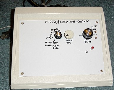
| Here's the PSK/SSTV receiver |
|
This unit WAS my "pride & joy" Hy-Gain project!
(See further down for the new one.)
By switching just one line on the PLL chip (160Khz) I can select either 14.070 or 14.230. (How convenient, eh?) Using the IF Shift, I can bring the desired freq range into the filter's passband. This also allows receiving weak signals in the presence of strong ones.
The switch on the RF gain pot serves as the selector. (SSTV thus has the RF gain at max.) The PLL locks the receiver onto the proper frequency, so no clarifier is needed. The IF shift does an excellent job with PSK, but because the filter is so narrow, SSTV is less than ideal. This receiver was intended for PSK, anyway. SSTV was just an easy "bonus".
| Inside the PSK/SSTV receiver |
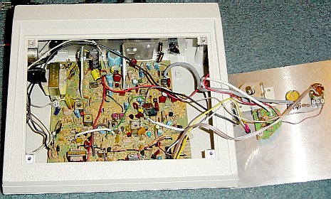 |
(Click HERE for extra-large, labelled version.)
The small IF shift osc board was "snipped" from the Hy-Gain board that became the WFIF receiver. (See how BTN can be so practical!? Gotta love this stuff!)
THIS CB board conversion is now my Pride and Joy project!
| My digital receiver/VFO, in early stages of development |
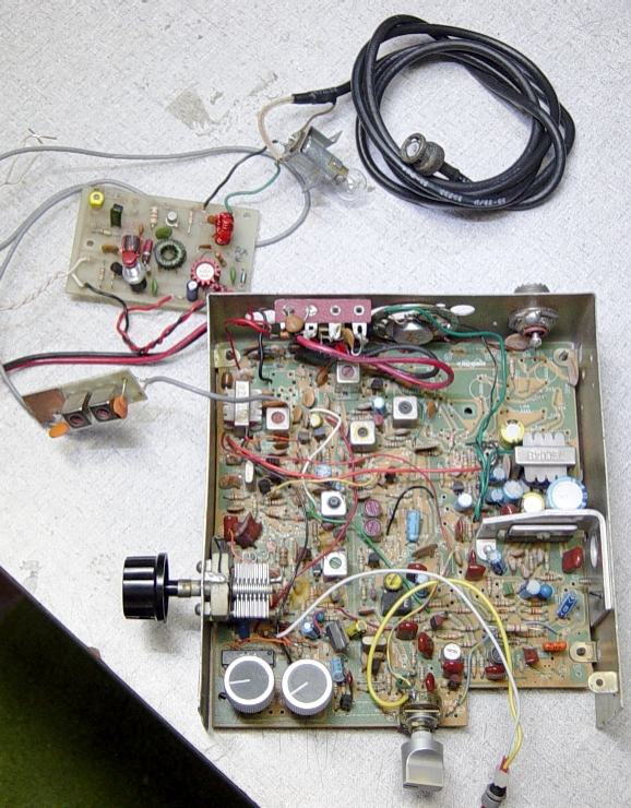 |
In this pic, you can see that all of the parts for the CB transmitter system have been removed. (I later added a specialized, low-power output for the exciter system.)
The PLL system is fully operational across the entire 75/80 meter band. It gives me 5Khz increments. The variable capacitor protruding at left, gives me a NICE, smooth 0 to +7 Khz, so there are no "gaps" in frequency coverage!
At this stage, I was using an 80 meter "Two-Fer" transmitter to boost the output of the RF generator of this unit. It worked, but was cumbersome. The light bulb was the dummy load for the "Two-fer". The small board with two "IF" cans is the LPF, fed by the transmit mixer of the board. In this configuration, it had two, 4-bit binary, rotary switches for frequency selection. It was a bit of a pain, so I generally just kept it set to 3,885.
I had used this configuration only a handful of times on the air. It was just too combersome and delicate, what with that transmitter board hanging loose. I considered mounting it, but then decided to try a simple, single transistor approach... after all, the input to the "B.O.B" is fairly high Z. With just a few new holes drilled, I was able to install all of the parts onto the existing PC board. It all worked quite nicely, in fact! See next pic, below.
| The V4.2 "B.O.B" with new digital VFO V1.0 |
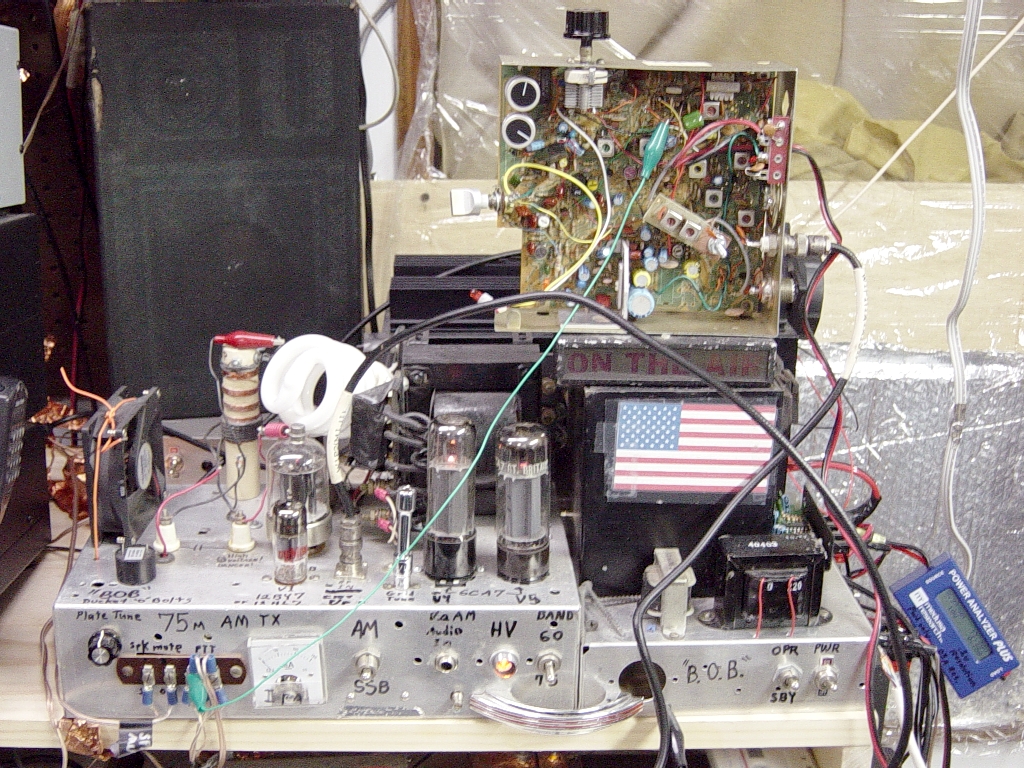 |
This was the mid-point of my progress developing the new PLL controlled VFO for the "Bucket O' Bolts" transmitter. With the addition of this piece, it is no longer just a transmitter... it is a SYSTEM! :)
The LPF is now mounted inside the case. The RF amplifier is installed directly onto the existing PC board. It is just a 2N3904 and a tuned ckt. It provide approx. 6~10v P/P output, which is more than enough to drive the "B.O.B." transmitter to full output. It all looks great on the scope! :)
I had a number of nice QSO's on it in this configuration, to verify that this design was working! Sure enough, it is! Let's just say that I am a very happy camper. :)
| The V4.3 "B.O.B" SYSTEM's new digital VFO V2.0 |
 |
Ahhh... now we've gotten to the GOOD part! :)
With my ribbon microphone connected to this "B.O.B." station, I can now say, with absolute truth...
"This station is HOMEBREW, from the microphone to the antenna!"
Here is PHASE TWO of the design & implementation of the new receiver/VFO. I've created an "address translation table" in an EPROM to translate the binary output of those numeric thumbwheel switches into the correct binary code for the PLL to correlate it with the frequency shown by the switches. The operation is so simple, it's elegant! :) The LED digit display shows either 0 or 5, for the 5Khz, which is controlled by a toggle switch. (Not shown.)
If you look carefully, you can see that the operating frequency is 3.885 :)
The EPROM is encoded to only operate the PLL from 3500 to 3995. Outside that range, the VFO output is disabled, and the PLL goes "on vacation" until a valid frequency is dialed in. Since only 7 bits were needed to give me the 500Khz range, I used the LSB of the EPROM to control the RF output stage. Only valid frequencies will enable it. (I've also used it in the 3600Khz portion of the band. 100% success!)
With the EPROM running steady-state, there is no clock, no noise. No need for a CPU... the thumbwheels are connected to the address lines of the EPROM. I whipped-up a GWBASIC routine to generate the proper sequence of bytes, and burned them into the EPROM. It took a couple tries to get it right, but once I had it working, I was VERY happy with the results! There is a red/green LED just to the left of the EPROM, for tx/rx indication. (Hey, why not??)
I've so thoroughly modified this former CB, that it is certainly fair to call this a HOMEBREW receiver/VFO! :) Now, all this baby needs is some kind of decent cabinet, so all of the controls & display are mounted nicely.
(By itself, this unit WILL work as a very QRP CW transmitter. It just needs a BFO for receive.)
Sure, this COULD have all been done with modern chips... but WHY NOT re-use some of this good old 1980's technology? You can get 2732 EPROMS as throwaways, now! I probably have several dozen of them!
Look for more projects to come! :)
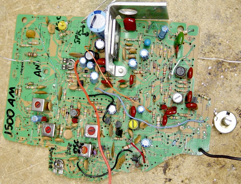
| 75 meter variable-tuned RX |
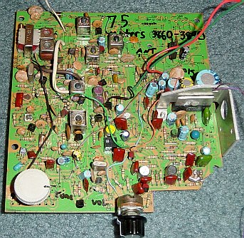 |
This one uses a pot to vary the voltage to the varactor diode of the VCO. Because of the large capacitance needed to move it from 37Mhz down to ~14, the full range of the varactor is only about 35Khz, but that's perfect, as it covers 3860~3890, which is the portion I was interested in covering, anyway. The "TX-offset" x-tal osc functions as a BFO so that I can also copy SSB when needed. The tune control, itself, serves to clarify the signals. The ceramic filter is about 10Khz wide, so SSB reception has lots of "monkey chatter" above & below, but it works OK as a monitor radio. The real purpose was to listen to the AM Window, anyway. There are still a few GOOD guys there, and they are the ones I enjoy QSO'ing and listening to. The belchers & crude ones are a non-issue, as I tune them right out.
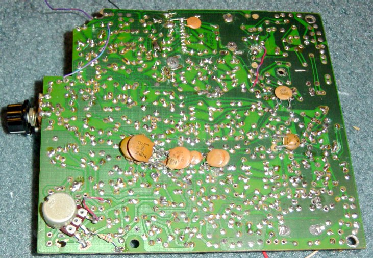
| Bottom view of 75M board |
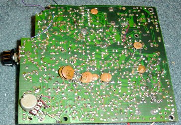 |
The reason for those "piles of capacitors" is because I did not have any NPO's of large enough value, so I had to parallel the smaller NPO's that I did have at the time. It worked OK. After obtaining some new NPO caps, I've removed that unruly "pile". The VCO and the VCO buffer cans both needed larger value caps to move them from 37Mhz to ~14. (~14Mhz - 10.7Mhz IF = 75Meter band)
The pot in the lower-left is the Tuning control. The resistor from the wiper to gnd helped to even-out the tuning range. (The tuning range was "bunched-up" at one end, due to how the varactor works.)
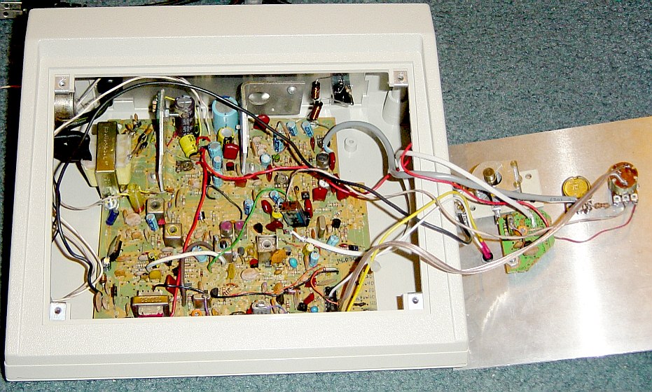
| WFIF, 1500Khz receiver board |
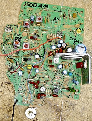 |
Here's the board that receives WFIF. I replaced the first two RF cans and the 10.7 IF cans with standard AM radio oscillator coils. With a 22pf cap across them, they resonate on 1500 Khz. Another of these cans is used as the LO. There is a small trim-cap in the ckt where one 10.7 Mhz can used to be. This adjusts the RF feedback here, providing for some Q-multiplication and improved selectivity. This was done to compensate for the removal of the 10Khz ceramic filter. I wanted ~20Khz total bandwidth, which this now provides. The sound is quite good, even with a fairly weak signal.
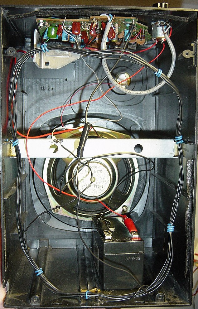
| WFIF, 1500Khz receiver unit |
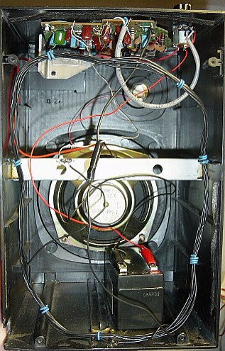 |
Here is the 1500 board inside it's "home"... a cheapo stereo speaker cabinet. :) It really cranks pretty loud, and sounds decent. The board is mounted upside-down to the top of the cabinet with the power/volume control nearby. The small gel cell at the bottom was used only for testing. The antenna is simply 6 turns of wire wound wround the inside of the cabinet. Sensitivity is quite good. Having three TRF stages followed by 3 IF stages helps! :) I later added shielding to the loop and made a few other refinements so that this unit would pick up WFIF's signal within the very powerful near-field of WDJZ, which is only 30Khz above WFIF! I used a UL Listed "Wall Wart" to provide power, and gave this radio to a lady in my Church. She loves it! :)
- The Wouff Hong -
It once struck terror into the hearts of LIDS, everywhere...
Whatever happened to this instrument of law and order??
|
You are welcome to E-mail me with comments/suggestions.
Constructive messages are welcome.
Abusive messages will be deleted. It's that simple. :)
Here's my HOME page
*** DISCLAIMERS ***
(Keep the lawyers happy.)
*ALL* Information presented here is done so without warranty or guarantee of any kind. Author assumes no responsibility for the use or inability to use this information. Author also assumes no responsibility for the ability or inability to complete the projects, above. These projects do not use any lethal voltages, but care is still advised, as batteries can provide enough current to cause burns if short-circuited.
This information is presented as educational information only. No guarantee is made as to its fitness for any purpose. All risk is assumed by the person who choses to use this information. While the author's experience indicates that this proceedure was effective, any attempt to build/modify these devices IS AT YOUR OWN RISK. Extreme care must always be excercised, this is at the builder's SOLE RISK.