
God Bless America!
N1NKM's PSK31 ELMER page |
|---|
|
|
WHAT IS PSK31?"PSK" stands for Phase-Shift-Keying. 31 means 31Hz.
|
|||||||||||||||||||||||||||||||||||||||||||||||||||||||||||
| PSK31 RX ONLY |
|---|
 |
| This is the most simple configuration possible: Receive only. No interface is required. Use this setup to verify that your computer is capable of running the desired software, and that it is getting a useable signal from the radio. It will also give you opportunity to watch how the QSO's are done.
There are some modern rigs with BUILT-IN digital/soundcard interfaces, which connect directly to the USB port of the computer. Operation of these are beyond the scope of this page. |
| Typical PSK31 Station |
|---|
 |
| This is a typical setup, using a common rig interface device, IE: RigBlaster ™.
Most rig interface units operate alike, with various features and options depending upon the manufacturer and model. NOTE: This basic configuration is the same for ALL computer-based soundcard digital modes. |
| Modern PSK31 Station |
|---|
 |
| This is a typical MODERN setup. This uses a USB rig interface device with built-in soundcard, the operation of which is beyond the scope of this page. |
Follow the instructions with your interface unit to get it going, then follow the advice given here on this page to get your signal "tuned-up" and looking great on everyone's waterfall display!
| BASIC setup guidelines |
|---|
| Once you have tuned your rig and antenna, the most important step is to ADJUST the audio levels coming from your computer, through the interface device, and into the radio.
In the Windows Volume Control window, you want to set the "MASTER" and "WAVE" controls to 1/2, as illustrated, below: 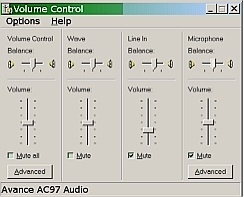 Set the level control on your interface (if it has one) to 1/2. Set your rigs' RF OUT to MAX, then set the MIC GAIN to MIN. Start the computer transmitting. Your rig should switch to TRANSMIT. Check your wattmeter. It should read zero. Turn up the mic gain until you read 20 watts (or 1/2 your rig's maximum output, whichever is less.) Your MIC GAIN should be somewhere between 1/4 to 3/4 range. If it has to be set down around "1" then lower the audio from the computer to 1/4 and try again. You should ALWAYS see ZERO "ALC" on your rig! This is critical! If there is *ANY* ALC, then you are distorting, and thus transmitting a WIDE signal. This is to be AVOIDED at ALL COSTS, as it causes considerable QRM! (ALC is usually visible on a meter, either directly or by pressing a button.) Note that on MOST RIGS, "ALC" is not a user control, it is internal. (ALC = "Automatic Level Control") It is designed to protect the finals of your radio from being overdriven. When there is too much audio input, the ALC circuits "clip" the audio, introducing significant distortion. When operating PSK, this not only causes a lot of QRM, it also wastes power in your transmitter on useless (as well as harmful) signal emmissions. You also want to set Windows to "NO SOUNDS" in the Control Panel. This will prevent your Windows "dings" and "YOU'VE GOT MAIL!!!" sounds from being transmitted! |
Here is a picture of PSK31 and PSK63 signals, side-by-side.
I have modified the default spectrum colors used in DigiPan to be more "rainbow" like, better conveying intensity. It is this custom pallette that I use in all of the screenshots on this page. Here is a screenshot of that pallette that you are free to copy. Try it, and you will see that it makes the waterfall much more informative than the default! If you are seeing RED traces, your receive audio level is too high. Lower the volume on the radio a little.
Some of these screenshots were made with my old Drake TR3, and some were made with my Icom IC718. There is relatively little difference, as long as you are using a good receiver.

PSK31 info & advice
This page displays some images of various PSK31 signals along with explanations & operating tips. Please pass this URL along to others and post it in HAM Newsgroups, Clubs, WEBsites, etc. :) You are welcome to LINK to this site, also. Please let me know if you do! N1NKM2(at)AOL.COM (Yes, there is a 2 in the e-mail address.)
Here is the URL, to CUT & PASTE: www.mymorninglight.org/ham/psk.htm
NOTE: You can NOT link directly to ANY of the graphics on this site! You MUST ONLY link to the PAGE, itself. Thanks!
| PSK31 Figure 1 |
|---|
 |
| Here is some typical PSK31 activity on 20 meters. The numbers & markings at top are AUDIO frequencies. Zero Hz would be equivalent to 14.070Mhz, which is the "bottom" of the 20 Meter PSK31 "window". Signals "enter" the screen at the top and scroll down, resembling a waterfall. (Thus, the name!) The blue background is the "white noise". It takes approximately 20 seconds to scroll from the top to the bottom. In my DigiPan configuration, signals go from cyan to green to yellow to orange. Typically, green & yellow/green are normal. Yellow is strong, orange is EXTREMELY strong. (The software used here is DigiPan. The colors can be customized. I chose RED as the absolute clipping limit color. The default is bright yellow. My custom pallette is shown further above.) 3 = Strong signal, with mild sidebands. RSQ = 587 4 = weak, steady carrier 5 = an ongoing QSO: RSQ of sta.#1 = 119, RSQ of 2 = 449 6 = a steady carrier, probably a tune-up 7 = two weak signals, very close together 8 = a VERY WEAK signal RSQ=019 9 = another weak QSO (RSQ = 019 & 239) 10= a HORRIBLE signal!! RSQ = 343 11= a QSO; one weak, one good signal (RSQ of good =559) 12 & 13 = markers for my TR/3's upper audio BW (2300-2400hz) |
Item #10, above, is a VERY WIDE signal! This type of distortion is usually caused by using the built-in Mic Processor in most modern radios. YOU NEVER want to have the Mic Processor active with PSK31! A wide signal like this has the potential to interfere with several others on either side. That is a "No-No!" He is occupying over 300 hz! That's about 7 or 8 QSO's wide!!! You can also see the effects of QSB (fading) on this signal. the fading is most obvious in his "sidebands". Compared to some foreign stations I have seen, this guy's QRM is mild! I have seen signals which literally occupied TWO THIRDS of the window!!! That's about 1600hz wide!
(Scroll down for something REALLY WILD!!)
| PSK31 Figure 2 | |
|---|---|
 |
1 = an example of a GREAT signal! The diamond marks the RECEIVE freq, the little red "flag" is the TX. (The offset is due to my old tube rig's freq. drift! SOMEDAY I will update these pix with signals captured by my new Icom rig!) I was in QSO with this person when I snapped this screenshot. "RSQ"=589 2 & 3 = Moderate signals, showing severe QSB (RSQ=449) 4 = somewhat weak signal with QSB (fading) |
| NOTE: The double-lines in the signal are where the operator stopped typing. This is referred to as "idling". Most PSK31 software will give an "IMD" (InterModulation Distortion) reading when an "idle" is received.
Signal #1 is as good as a PSK31 signal can get! The "edges" are very sharp. There are no sidebands. Although they are much weaker, the other signals shown here are also good. |
|
| PSK31 Figure 3 | |
|---|---|
 RSQ=456  RSQ=575  RSQ=551 |
Here are three examples of BAD SIGNALS. The sidebands are very obvious, and are being affected by QSB. That is why they are not constant. Since they are weaker than the main signal, the visual effect of QSB on the sidebands is greater.
The TOP signal is not as severe as the second one. The bottom one is HORRIBLE! I count 12 sidebands coming from the lower side of that one! It is very likely that these operators have their Mic Processors (or "compression") turned on. That is something you definately DO NOT want to do, because this is the result! <:P NOTE: These are not RFI problems, these are audio drive problems. Please scroll down to figure 9 for more information, and some good advice to HELP stations like this! :) |
| PSK31 Figure 4 | |
|---|---|
 |
Signal #1 (left) in this image is "idling". His audio drive is too high, which is causing the very noticable sidebands next to the two solid lines. He is probably in the process of fine-tuning his station. "RSQ"=557
The other signal (#2, on right) is good. "RSQ"=558 |
|
|
Here, at #1, we have a moderately strong signal, with some fairly nasty sidebands. "RSQ"=557
Notice how the signal at #2 is "bent"? This is caused by his transmitter's frequency drifting. This is especially problematic with older analog and tube rigs. |
| PSK31 Figure 5 | |
|---|---|
 |
Here are two examples of GOOD SIGNALS.
The top one is STRONG, as evidenced by the yellow in the middle. This kind of signal is always 100% print, unless there is SEVERE QSB and/or QRM! There is only the very SLIGHTEST indication of sidebands, here. "RSQ"=589 The bottom one is average strength, and nice & clean. This signal will almost always yield nearly 100% print, possibly only dropping 1 letter every now and then with QRM or QSB. "RSQ"=559 |
| PSK31 Figure 6 | |
|---|---|
 |
Signal #1 (left) in this image is "fuzzy". This is common for DX signals, due to the great distances travelled. RSQ=449
Signal #2 is "idling". RSQ=?59 (Nothing printing!) #3 & #4 are very weak, DX stations, as evidenced by their "fuzziness". #5 is someone keying and unkeying their transmitter. |
| PSK31 Figure 7 |
|---|
 |
|
1 = Very weak, DX signal, "RSQ" = 219 |
| PSK31 Figure 8 | |
|---|---|
 WHAT on God's green Earth is THIS?!?!?!?! I captured this extreme oddity Sunday Evening, 5/26/02 while enjoying a nice QSO. (Red diamond, on far right of image). This extremely weird signal started off looking a little like someone with RF feedback, about 200Hz wide, and wavering back and forth, a little like the narrow end of a tornado. I waited a few seconds before realizing that I was watching something really unusual! It started getting wider and wider! I waited until it completely filled the screen, top-to-bottom, and it just about made it side-to-side as well! (It was well over 2khz wide when it stopped.) It had a very strange warbling sound in the speaker... like someone's rig was REALLY going berserk with feedback! If I gave a RSQ, it would be 070! I decided to post it here, simply because it was SOOOOOO WEIRD!!!! As you can plainly see, it obviously caused some significant QRM to several QSO's that happened to be within it's wake. Wow! What a wild scene! |
|
Everyone I have QSO'ed with about such things, has appreciated the input! We need to help each other, here... if you see a terrible signal calling CQ, LET THE STATION KNOW in a polite way. By observing when he keys and unkeys, you can quickly determine whether or not his station is causing the problem. The interference will ALWAYS track EXACTLY with his transmissions, starting and stopping when he keys and unkeys.
Here are some suggestions to offer to the station with a bad signal:

#1 Make sure that the Mic Processor is turned *OFF*.
I cannot stress this enough!

#2 All SSB rigs have an ALC circuit, and a meter reading for it. This must
be at ZERO! You will need to turn the audio coming from the computer down
first. The little "speaker' icon in the lower right corner (of Windows) gives
you the volume control "sliders". You should have the MASTER and the WAVE
controls set to the middle, or slightly less. If you have the computer
"slider" controls down below 25% and there is still a reading on the rig's
ALC meter, you will need to turn down the audio control on your interface box.
Some have a knob, others have a screwdriver slot.

#3 Here is a quick way to set power: While sending an "idle" signal, turn the
control up until you see the ALC meter just begin to move. Now, switch to
your wattmeter, and turn the control down until your transmitter power
decreases by about 1/5'th. (If you were transmitting 50 watts, you will now
be at 40. If 100, you will be at 80.) That should get you within tolerance.
Relying on another station's report can help you fine-tune. You may find
yourself dialing power down to 20 or 30 watts. THIS IS STILL PLENTY for this
mode! :)

Finally, #4 - GROUNDING. Make sure everything is tied to a common ground!
One good way to do this is to power everything from the same power strip.
This also prevents "ground loops". A small capacitor across the mic input and
computer audio output may also be necessary to reduce any RFI-induced problems.
Believe me, helping him helps EVERYONE enjoy PSK31 even more! :)
| PSK31 Figure 9 | |
|---|---|
 This is an example of some nasty RF feedback! (Note: The slanting of signals was due to frequency drift in my Drake TR/3 before I modified it.) I was working with this gentleman (who's call & name appear in lower left) to help him resolve this problem. He was trying several different connections, power levels, etc. but we were unable to correct it on this attempt. The actual QSO was taking place near 1800hz, marked by the red flag & red diamond. The trace below the small blue triangle was another QSO. (The band was fairly quiet when we were trying this.) His RSQ is 562. There are 4 distinct traces below his main signal. The left-most trace (between 300Hz & 400Hz) is very faint, because the response of the Drake TR3 receiver I was using falls off RAPIDLY below 600Hz. There is a faint trace visible above him, around 2200hz as well. In the receiver speaker, it had a very distinct "hollow whistle" sound, which is typical of RFI on an SSB transmitter. I have seen him on the air since, and it looks like he has solved all of his problems! His signal is one of the better ones, now. :) |
|
| PSK31 Figure 10 |
|---|
 |
|
8 = a WEAK signal, also being QRM'ed The station at ref. # 7 is the "offender" in this display. His "primary" signal looks almost normal, except for the sidebands directly adjacent to it. Observe carefully, how the small, evenly-spaced vertical lines perfectly coincide with his single-tone "end transmission" signal! He was obviously testing his station, having keyed, unkeyed, then keyed again in quick succession. You can also see the vertical "waves" of lighter blue areas, extending out on both sides of his signal. This is all the result of RF getting back into his audio circuits. This is causing a LOT of QRM across the ENTIRE waterfall! (RSQ=551) Also notice the spacing... they appear to be 60Hz apart. He most likely has a serious ground-loop problem, and the 60hz is mixing with his signal, and producing all kinds of nasty artifacts. |
| PSK31 Figure 11 |
|---|
 |
|
7 - This is the STRONG signal. 8 designates where one of his sidebands may be interfering with a QSO that is right nearby. You can very clearly see the difference in the "noise floor" when he unkeys... the background suddenly changes from dark blue & black to light blue & green! His RSQ would be 596, the "6" being due to the very strong sidebands. The effect is due to the receiver's AGC being activated by the strength of this signal. The receiver automatically reduces it sensitivity when a strong signal comes in. This is perfectly normal, and on SSB, is very desirable! It prevents a strong signal from knocking you out of your chair, if you had the volume up to copy a weak one. The AGC automatically reduces the volume, almost instantly. Because PSK is so narrow, there are literally DOZENS of QSO's within the same bandwidth as a single SSB "voice channel". When ONE strong signal comes in, the gain for the whole bandwidth (about 3Khz) is decreased. If I had a NARROW filter in the rig, centered it on one of those weaker signals, and made sure he was outside the filter, this would not happen. |
| PSK31 Figure 12 |
|---|
 |
|
2 = Strong signal 3 = another weak QSO "Unkeyed" shows the normal RX noise "Peak" shows max desense when his signal peaked. You can clearly see where the effect of QSB on the strong signal causes the background noise to rise. The weak signals also increase when the strong signal's desense decreases. As explained above, this is NORMAL BEHAVIOR for the radio. |
| PSK31 Figure 13 |
|---|
 |
|
Here you can see the effect of fast QSB on a strong signal. (RSQ=598) The thin horizontal lines are where the receiver is less desensed, and the noise floor rises. These are like a quick "fwiff fwiff fwiff" in the speaker. A very brief, deep QSB caused the strong horizontal line, highlighted above. Again, this is NORMAL behavior for the radio. The effect can be changed if you have a "FAST/SLOW AGC" control on your rig. In the SLOW mode, fast QSB would not cause the horizontal lines, but would most likely weaken the desired signal enough to cause a letter or two to be missed during the fades. |
If you found this page useful, I'd like to hear from you! :)
N1NKM2@AOL.COM (Yes, there is a 2 in there.)
This site was originally created in the EARLY 2000's. I have attempted to update things here and there along the way. In Nov 2023, I removed a few dead links, and made some minor changes. Most of the information here is still relevant. I have noticed much less activity in the PSK31 mode in recent years, but it is not yet "dead". I hope the info here encourages you to get on the air with this great mode! :) 73 de N1NKM
Return to the N1NKM HOME PAGE