Page last updated: 3/11/2018
 |
The FRAME can be made of any non-metal material: Wood, styrofoam, plastic, cardboard, Etc. The dimensions given are only approximate... adjust as needed. You can make use of almost anything that is on-hand. Depending on what you have for materials, it is possible to build this antenna without spending a dime! (Several have been built using the square styrofoam packing material from various shipping boxes.) |
 |
Begin by wrapping wire around the frame, A-B-C-D back to "A" 12-18 times. The loose ends will be connected to a TUNING CAPACITOR. The wire should be somewhat tight against the frame. Bascially, ANY diameter of wire may be used, from 30 guage up to at least 18, although it becomes awkward to work with at either extreme. 24 guage seems to be the best to work with. You can use regular insulated or enamelled. The wire is not very critical. Note: Here is a link to a site that will calculate the MilliHenries of the coil. You want to be around 250 for a standard AM tuning cap to cover the band. Coil Calculator link. This way, you can figure out the exact number of turns you need for the size of the coil you're making. |
 |
Once you are done with the winding, the wire should be taped or glued down at each corner, as represented by the gray area in this diagram. (Tape is recommended until the proper number of turns is determined.) The actual number of turns may need to be changed, depending on the size of the frame. Larger frames need less, smaller need more, you may have to experiment. (Using the calculator link above, will reduce the amount of trial-and-error.) The Tuning Range should cover the AM band: 540 to 1700. More turns brings the range down, (500-1580, for example) less turns brings it up (580-1750). The actual range depends on the range-value of the tuning capacitor and the number of turns turns vs frame size. Normally, combining both sections of a typical AM tuning cap will yeild about 600pf when fully meshed, and about 60 when open. With a 12-turn coil on a 14" frame, this range goes well above and below the typical AM band, so you should have no problem picking up stations. Using a single-section capacitor means you will most likely need to wind 18 turns. Don't be afraid to EXPERIMENT. :) |
 |
The tuning capacitor can be salvaged from a "junk" transistor radio, or purchased from an electronics supply store. The 3-pin type are found in AM-ONLY radios. The 6-pin type are typical in AM/FM units. You will need to examine the radio to determine which terminals you will use. On the 3-pin units, you will always use #2. The other terminal you want is the one which has a wire coming from the radio's built-in antenna coil. (assume it's #1) You would then connect the ends of the wires from the LOOP to terminals 1 &2. With the 6-pin, look for that wire to the coil. You will use that pin, and the center one. (either 2 or 5, whichever is right next to the one with the wire.) You may need to connect pins 1 & 3 together (or 4 & 6 on a 6-pin unit) to get better low-end range. The typical variable value should be in the 30-400 Pf range.
Here is a source for a good tuning capacitor. (About $20) Note that it is somewhat large, but will work just fine. I have purchased several of these, and they are EXCELLENT quality! midnightscience.com These are single-section caps, and should work fine. There are only two connections, one to the frame, then any one of the four lugs. (All 4 lugs are the same connection point.) |
 |
To use the loop antenna, (light grey box) place it next to the AM radio which has been set to the desired station.(dark grey box) NO CONNECTION IS NEEDED! You may need to rotate the loop from side-to-side, but always keep one side close to the radio. The position of the antenna and the radio will need to be experimented with, as well. This diagram is only a rough guide. This antenna is directional, which can be useful in bringing in the desired station and reducing interference from others. Adjust the tuning capacitor for the loudest & clearest sound. The tuning may be very sensitive, so turn slowly. |
 |
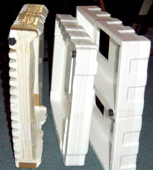
| Photos of 3 completed units | |
|---|---|
 |
 |
These are three units that I made from scrap styrofoam packing material. The unit on the left was about 10-15 years old when I took this pic around 2001. The one on the right was about 10 minutes old. :) All three of them work virtually identically. Unfortunately, the mini tuning capacitors I used in them are no longer sold at Radio Shack... and now, THEY no longer exist! (I had a bunch of them in my parts bin that I used to make these loop antennas. A suitable unit is given in a link, above.) | |