Installing the $6 DC-DC convertor into the Braille Display
PLEASE NOTE: There are 16 (small) pictures here, so please be patient while the page loads. :)
This page contains the JPG photos illustrating the replacement of an EXPENSIVE DC-DC converter used inside the Telesensory Systems Braille display device. The manufacturer of the original module wants $115 for it!!! This is absurd, so I set out to find an economical replacement. I found a small battery-operated flourescent lamp that could be easily modified to replace that expensive module... for under $10, retail! (See previous page.)
This page shows the installation of that modified lamp module into the Braille Display.
* WARNING * this unit will generate 200 volts dc or more! BE CAREFUL when working with it! The capacitor can store that charge for some time, and the risk of a painful electric shock is very real, especially when the unit is operating!
| The front of the unopened unit |
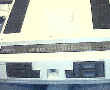
Here you can see the Braille display's
cells of pins. These little pins will raise
and lower to form the Braille letters.
Below these on the left and right, are
the clusters of control buttons. |
All of these pictures are with the unit upside-down, Braille cells toward you:
| Disassembling the unit: |
Remove battery & bottom cover,
exposing the electronics.
(Be careful of small spring-loaded
buttons that hold the battery
in place.) |
These are the small, spring-loaded buttons.
Be careful not to lose them! |
Here are the buttons, placed close
to where they came out. |
| We continue with the disassembly: |

The power connector is
on the left in this pic.
The small, rust-colored
connector seperates to
allow removal. |
Power connector (center)
seperated. |
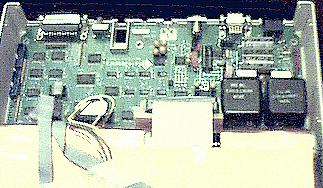
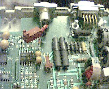
The main board slides out by
lifting and pulling toward front.
The two modules are lower right
in this photo. |
| Disassembly, cont'd & prep for new module: |
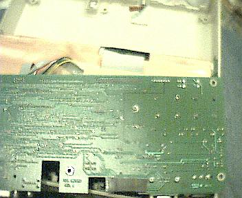
This is the bottom view of the Main Board.
The pads for the two power modules
are at the upper right in this view. |
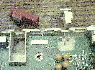
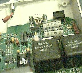
This is a closeup of the power
module connections, marked to
show in/out and polarity. Measure
HV with voltmeter on 1000v scale.
Voltage should be between
180-220 vdc. A failed module will
always have LESS than 100vdc. |
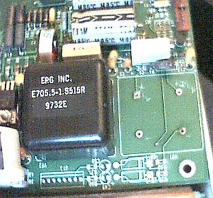
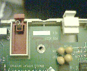
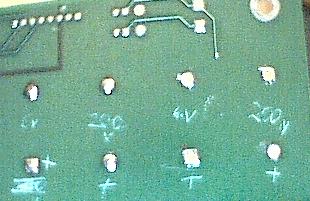
This is the top view, with the
faulty module removed. I marked the
positive & neg in and out connections.
The HIGH VOLTAGE is to the right. |
| Note: You will need to power the unit up to test the modules. This can be done by carefully connecting alligator clips to the two pins of the now disconnected power connection. (The rust-colored connector; see above.) The pin closest to the two power modules is positive. Apply 9 to 10 vdc. There should be approximately 6v at the inputs of the two modules, and between 180-220vdc out. A failed module may become HOT, or will have less than 6v in, and always LESS than 100vdc out. You will want to desolder the faulty module, and discard it. Remove any excess solder from the pads. |
| Installing the new module: |
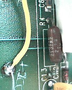
This image shows where
a resistor came loose, due
to excessive heat caused
by the failed module. It
needed to be resoldered.
|
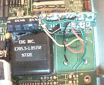
Here is the new home-made power
module installed. I used red and black
wires for the 6v side, yellow and
green for the HV. Yel = positive. |
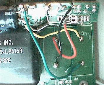
This is a better close-up picture of the
new module installed, with clear detail
of the wires for the 6v side & the HV. |
| Finish installing the new module: |
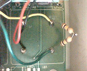
This image shows where a pair of 100K
resistors may be needed, if the
high voltage exceeds 250vdc when
no Braille cells are active.
|
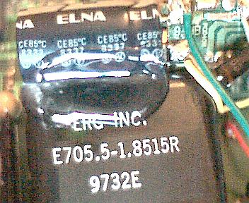
This is where the new home-made power
module is glued to the old (good) one
to prevent it from moving. |
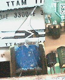
This is where the new
module's transformer is
glued to a nearby capacitor
for more strength. |
CONGRATULATIONS!
The installation is complete! However, the Braille Display should be tested before reassembly! It may or may not be necessary to add the bleeder resistors, as shown above. Only by measuring the high voltage of the new module, can this be determined. If the voltage goes above 250vdc with none of the Braille cells active, then the bleeder resistors will be needed to help "load" the voltage down.
These Braille Displays have BUILT-IN DIAGNOSTICS, which are accessed by holding the top horizontal control button of the right cluster IN when power is applied. (This can be tricky with the unit upside-down and all apart!) The tests can be advanced or changed with the buttons on the left cluster. One of these tests alternately raises and lowers ALL of the pins simultaneously. Other tests will raise one cell at a time, sequentially. There are other tests, too numerous to mention here. Chances are, the person you are reparing this unit for will be more familiar with those modes, and may be able to help you step through the tests.
It is normal for the DC voltage to drop as low as 100vdc when *ALL* of the Braille cells pins are raised! This is normal, however... and since ALL pins are NEVER raised during the display of normal Braille, it is not likely for this reduced voltage to be a problem. I have now sucessfully repaired TWO of these devices, and the owners are overjoyed at having them back. They now work perfectly!
This page is now complete! I am excited about this project, and want to help as many Visually Impaired people as possible! SPREAD THE WORD! :)
Please E-mail me with comments/suggestions.
Return to previous page
Return to HOME page
*** DISCLAIMERS ***
*ALL* Information presented here is done so without warranty or guarantee of any kind. Author assumes no responsibility for the use or inability to use this information. Author also assumes no responsibility for the ability or inability to complete the modifications, above.
Since Telesensory Systems no longer manufacturs these Braille Displays, finding competant technical support for them can be difficult and/or EXPENSIVE. Repair of these units as shown above, is done SOLELY AT THE REPAIRER's and CUSTOMER's RISK. (No endorsement by the manufacturer was given, nor should be implied.)
This information is presented as educational information only. No guarantee is made as to its fitness for any purpose. All risk is assumed by the person who choses to use this information. While the author's experience indicates that this proceedure was effective in repairing a failed Braille Display device, any attempt to make these repairs IS AT YOUR OWN RISK. Extreme care must always be excercised, and it is strongly recommended that this proceedure ONLY BE PERFORMED BY QUALIFIED PERSONNEL. Again, this is at YOUR SOLE RISK.