
God Bless America!
N1NKM's HAM page 2 |
|---|
QRP! |
This page displays some of the very reasons I got into Ham Radio, in the first place!
HOMEBREWING & QRP!! :)
Since I became an EXTRA in November of 2001, my homebrewing activities have gained even more momentum! Hey, why not??? *NOW* I can build all kinds of nifty little transmitters... AND USE THEM! :) On this page are a few pictures, just for the fun of it! :) It is my hope that it will inspire YOU to go "junk hunting", and (if necessary) order parts, and discover the THRILL of firing up a rig that you BUILT FROM SCRATCH, and make contacts with it! It's even better than bulding/using a Kit, because *YOU* designed it (or refined it from some other schematic)! :)Even though I now own a NIFTY ICOM IC718 HF rig, I still will continue to build & experiment with QRP rigs, like these! Although I no longer need the 17M rig, below, I will keep it on this page just for those who may be interested. :) I've re-used the chassis & power supply to build a simple 12BY7-based driver for "BOB", my 50 watt AM transmitter. Sure, my ICOM will do 40 watts of AM... but as anyone will tell you, it's not **REAL** AM unless it's PLATE MODULATED! :) Heh heh! (I have gotten several glowing reports on my IC718 & D-104's audio quality. The dedicated AM transmitter is a tad better, tho!)
NOTE: The "heart" of many of these homebrew transmitters is a digital, PLL-controlled RF Signal Generator, which puts out about 10mw from 1.6Mhz thru 30 Mhz in 100Hz steps. It is used as the exciter in most of these designs, either providing a stable, unmodulated carrier, or a SSB signal, which is then simply amplified. The first QRP'er, below, used the SSB capabilities of this RF generator. It was little more than a "baby linear". I made several contacts with it! :) If you don't have such a device, you can usually "scavenge" an old CB for crystals, or maybe even move it's PLL & TX/RX up to 10, or down to 12. :)
Here is how you can move a TRC458 CB to 10M!
| 1-tube, 2 watts on 17 meters (OBSOLETE) | |
|---|---|
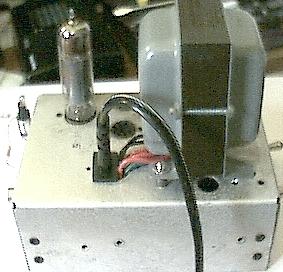 Top view, showing power transformer & 6BQ5 tube | 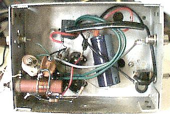 Bottom view, showing point-to-point wiring, RF-in BNC on right, RF-out on left. Chassis was part of a VERY OLD, broken CONELRAD receiver. |
Total COST to build this little rig... $5 for the BNC connectors & power transformer (surplus)! Everything else was "scavenged". ;) ** NOTE** This 17M rig has been dismantled, and rebuilt as a driver for the "BOB" transmitter. (The appearance is virtually identical, tho!) The tube is now a 12BY7 (wired for 6v filament). It takes the milliwatts output of the RF generator and boosts it to about 2 watts on 80 & 40 meters.
17 meters is a decent band for QRP! One of the things I like most about it, though, is ***NO CONTESTING***!!! You can use it without fear of being "trampled to death" by the incessant "CQ Contest" garbage that plagues the other bands from time-to-time. What a SHOCK I had, my first weekend after becoming an EXTRA: every HERTZ of spectrum on 80-10 (every band on my Drake!) was wall-to-wall with that mess! <:( That is what MOTIVATED me to build a rig to get me onto at least ONE of the "WARC bands"! They do say that necessity is the mother of invention!!
Hmmm.... I guess that stupid contest served a good purpose, after all... THIS RIG! :)
Here is a former CB (Lafayette MICRO 66), which has been re-tuned for the AM portion of Ten meters, up around 29Mhz.
(Let's have a moment of silence, to mourn Lafayette's demise . . . . . . . . )
| 10 meter AM rig, 29.000 - 29.200 Mhz | |
|---|---|
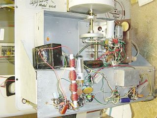
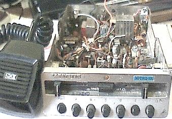 Front view, showing the control panel. The VOL & SQL are not used. Channel "E" is selected for the RF input. (E= External) | 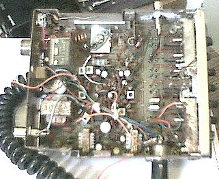 Top view, showing majority of components. Receiver out BNC is at bottom left. TX out at top left. |
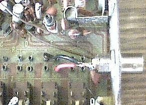 RF input connector, close-up. Only a few milliwatts are needed to drive the crystal circuitry. | |
I use the front-end of this rig as a pre-amp and T/R relay to facilitate switching the Rx in/out of circuit. The CB's internal transmitter & modulator are used basically as-is. The mic plug was rewired to accomodate a standard Radio Shack type CB Mic. I installed BNC jacks to send the receive preamp output into the general coverage receiver, and to bring the unmodulated RF from the signal generator into an empty crystal socket. I have made some contacts with this, as well! While it's audio isn't nearly as beautiful as some of those guys on the band, it's certainly clear enough to get through with only 4-5 watts! If I had a schematic of this baby, I could probably modify the audio amp/modulator, to widen it's frequency response... but oh well. <:(
This beastie is the "pride & joy" of my homebrew QRP rig collection! :)
| 75 meter QRP AM rig, using firebottles! | |
|---|---|
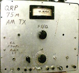 Overall front view. |
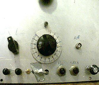 Closeup of main controls. |
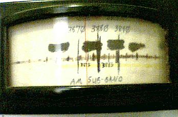 Closeup of VFO dial, showing 3873Khz. |
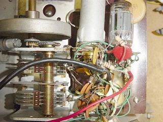 VFO & Buffer stages |
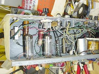 Underside, showing Mod & Final tubes |
 |
It started life as a CW-only transmitter, back when I was only a lowly Tech Plus. :) My friend, Randy (KA1UNW, SK 5/12/13) drew up a schematic which I used, and he also created a new dial scale. He took a sheet of paper, cut it to fit the dial drum unit, and then made the markings. The blacked-out areas on the dial are his old frequency markings. I was too lazy to cut another strip of paper... I guess I should'a used white-out! OH WELL! ;) It originally was marked from 3675 - 3725 Khz, the Novice CW sub-band.
In Jan or Feb of 2002, I re-tuned the VFO for the AM sub-band and modified the driver & final circuitry to permit nice, clean Plate-Modulated AM, using an external audio power amp. (Internal modulator stage added 12/9/02.) The modulation envelope looks REALLY nice on the 'scope, and sounds great on the air... especially considering it's only about 4 watts!
I call this one my "QRP Pride & Joy", because it's the FIRST transmitter I built from SCRATCH, and it is the one unit that I have spent the most hours working on. I worked at least 5 states with it, on CW, back in 1992. Then, it was only pushing about 1 watt. By reworking the power supply, I was able to push it to 1.5 watts AM. (Carrier)
A friend commented about the "thing held on with duct tape", so I figured an explanation was in order, here! ;) It is a small light bulb, which is used to indicate the dip in cathode (plate) current, when the rig is tuned up. Ya gotta love that duct tape! ;)
On 12/9/02, again with guidance from my friend Randy, (SK 5/12/13) I added an internal modulator stage and made a few more modifications to the final's grid circuit to stabilize things. With the internal modulator, it takes only a few milliwatts of audio input to drive it to a beautiful, 100% modulated signal. :) Yes, this baby is actually self-contained and airworthy! Unfortunately, less than 5 watts on AM is usually frowned-upon by certain ops, so operation with it is difficult at best. :(
FOOTNOTE:My BTN experiment with the salvaged computer sound card/amp didn't quite work out as planned, but it was a fun thing to try, anyway! :)
(12/04) This was my BIGGEST PROJECT, a "BOB" Although NOT a QRP rig (50 watts) I figured a link to it was appropriate, here. :)
I also had a homebrew 2-meter QRP repeater, designed to operate as a split-site machine with a 440 link. The controller is still on the plug-in prototype "breadboard", so I don't have pictures of any of it. It uses several HT's and one of those digital voice recorder boards. The DVR board has 2 different courtesy tones in it, a CW id, a voice ID, and a "Time-out" message. (It only has 5 "slots" for audio.) The controller is very basic, using a few 74-series chips, and a handful of resistors, caps, and transistors. There really isn't much to it! The ID timer is the 60Hz AC power divided by 32K, which comes out to 1 pulse approximately every 9.5 minutes. A couple flip-flops and one-shots handle the timing for the courtesy tones, TX "hang time" and ID status. (The ID will only fire AFTER the receiver has been triggered, and the TX activated.)
If I ever get this thing assembled onto a real PC board, I will take some pictures of it. It's been just a "parts pile" on that "breadboard", with alligator clips & wires going everywhere, for a long time! It was on the air for a few weeks, back around 1998 or so. It was only 1/2 watt, so it's range was less than 2 miles... but enough people lived within range, that it got some use during the time I had it running. :) The HT that I use for the TX has a small fan mounted to it, so that it can run 100% TX duty cycle, and not even break a sweat! I was only running it at 1/2 watt because of receiver desense. I don't have the $$$ to buy a set of "cans"... that's why this was meant to be a "split-site" repeater. The TX would be at my QTH, and the RX at a friend's. Unfortunately, that never happened. OH WELL. In the meantime, it languishes in a box, down in a back corner of my workshop. <:(
Here is how you can move a TRC458 CB to 10M!
So... that's it for now! Thanks for following this link!
Here are some pictures of my PSK31 audio interface.
That is another "pride & joy" project that I get a lot of use and enjoyment from! :) It also works well for my local 10 meter SSTV activity.
Here's a NIFTY 6v to 200V REGULATED DC-DC converter project!
Check back every now and then...
you never know what kinds of other surprizes I may plop onto here! :)
Return to the N1NKM HOME PAGE