God Bless America!
N1NKM's Homebrew AM TX & RX
This is THE NUMBER ONE of my "PRIDE & JOY" Projects! :)
(This page is the DETAILED version)
Here's the SHORT version.
N1NKM's

Tech Stuff! |
HOMEBREW!
"B.O.B."
(Bucket O' Bolts)
 |
Please note the following:
I don't get to work on this unit, nor get to tweak this page, very often. Some info may be outdated.
Last update to this page: 12/24/16 (Yes, Christmas Eve!) Hihi!
This transmitter is NOT a "standard" design! It is very unorthodox, due to my limited budget and having to work with the stockpile of junk parts that I have on hand. Therefore, even though this unit works quite nicely, please understand that it is NOT a recommended transmitter design, and I would NEVER use this kind of "engineering" for any kind of commercial use! This is strictly my HOBBY. :) It's something I do FOR FUN. This information is merely presented for those who are curious... I don't recommend you try this at home! ;)
Most recent NEWS in brief...
In December, 2010, I successfully completed the conversion of an old Hy-Gain CB circuit board into a nice, PLL-controlled exciter and receiver for this transmitter! It works *GREAT*! (It's a whole new life for some old CB's!)
The PLL02A chip has a pin that allows 5Khz steps, which allows full coverage by simply adding a variable cap to the master x-tal reference osc. A 2732a EPROM chip allows me to use BCD thumbwheel switches to select the operating frequency, while also preventing out-of-band operation. Very cool. :) I've been using this configuration on the air, ever since. I'm calling it B.O.B. V4.3 and as of this writing, (July 2013) it's the last revision I've made in some time. (Time is a commodity that there never seems to be enough of.)
With just a few tweaks, and changing modes on my RF generator to SSB, I can also use "BOB" as a linear amplifier. I made several contacts on 60 meters @ 40 watts, PEP this way, back in 2006.
NOTE to users with slow connections: this page has several 80K+ pictures, which may take a few moments to load. Please be patient.
This page contains photos of my homebrew, tube AM transmitter (called "BOB"- Bucket O' Bolts) which is sort-of still under development. ;) As of V4.3, this thing puts out 55 watts carrier, PLL controlled! (That's up from 12 watts w/analog VFO, when I started this whole kooky project.)
Visitors to THIS PAGE since 7/10/16  :)
:)
(Over 23,000 from 5/27/06 through 3/1/14)
| Here's how I started: The "BOB" V1.0, 12W AM |
 |
| V4.3 - 55 watt AM TX! (2016) |
.JPG) |
| The transmitter has the USA flag on it, because I made the thing right here in the Good Ol' USA! ;) I usually use my Icom 718 for the receiver when I'm on this transmitter. The VFO's receiver works, but it's only mediocre. |
Scroll down to see the construction of this beast! You can see more details about the digital VFO, HERE!
It's 55 watts with the RF driver built-in, push-pull modulator, and digital VFO/receiver! Yeah, she's come a long way, baby! ;) Note: The spiral lamp is used as an RF/Modulation indicator. (BTN!)
This puppy even has a little brother! ;) Check out "BOB Jr!"
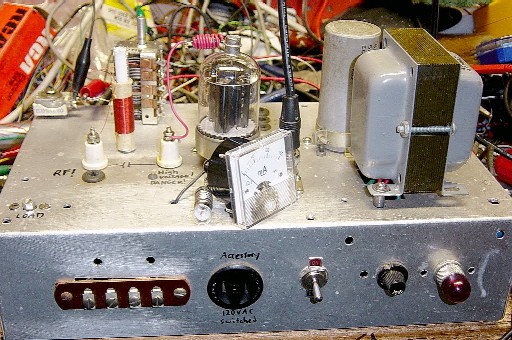
Following are some photos of the development & refinement of the unit. (V1.0, Dec 2004 to present.) In V1.0, only ONE 6146 tube was used. The 2'nd one came later. (That's a 14v bulb in series with the milliammeter. It has since been removed. This was where everything began. It boosted the 3 watt QRP transmitter to ~14 watts.)
The chassis came from a clunky homebrew automotive battery charger that I got from a friend who was unloading some JUNQUE. I wanted it primarily for the chassis! I got a nice, 12VAC 10A transformer, too! :) Hey, the price was right!!
From the looks of things, this chassis was something else before it was the battery charger. It may have been two things, who knows!? ;) That outlet (now repleced by the meter) wasn't connected to anything, neither were the screw-terminal strips on front. There were no capacitors, no tube sockets, just holes. Plenty of room to BUILD!
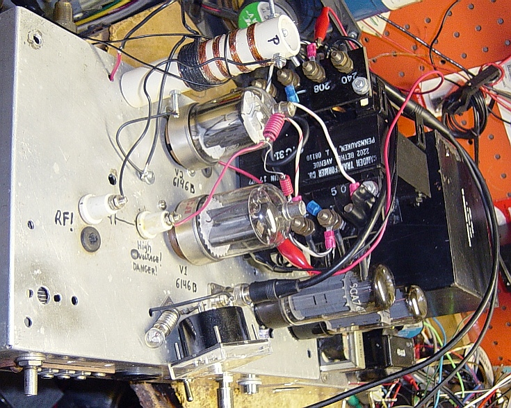
| Bird's-eye view of "BOB" V1.0 |
 |
Here, the RF IN BNC connector is clearly visible, as are the plate cap binding posts. (Obtained from that same friend who was unloading a lot of nice JUNQUE!) In this pic, I have the LOAD and TUNE caps labelled wrong. ;)
Here, the RF OUT is via the red & black alligator clips you see in the upper left, which feed into a 75 watt bulb as a dummy load. I also have a regular DL when I want to use a proper impedance load for real testing. A PL239 was installed shortly after this pic was taken.
The old output coil (pictured here) was wound on a cardboard form, about 1/2 or 3/8" diameter. It was supported by 1/2 of a "Papermate" pen barrel, which just fits a pre-existing hole in the chassis. ;) It was getting rather warm, so I replaced it with one of larger guage wire. The new, more efficient circuit (below) was even getting that NEW coil a little toasty! After I added the 2'nd 6146, I installed a beefier RF transformer.
Click pictures for larger view.
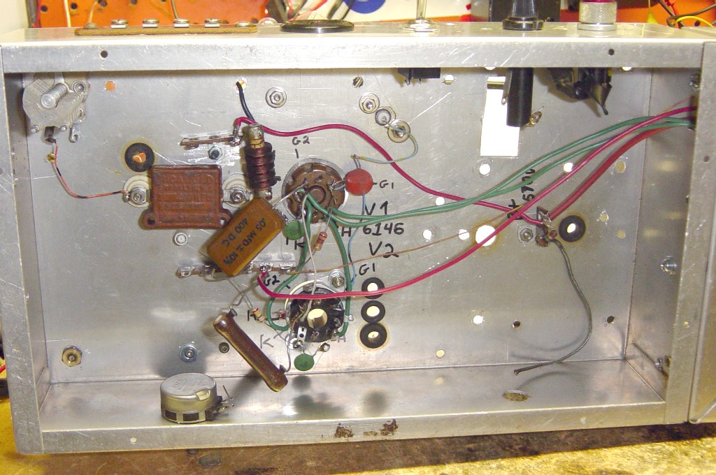
| Inside, bottom view of V1.5 |
 |
The brown square to the left of the tube is one of those nice "pancake" capacitors. It's a .01 at 1Kv. I have a couple more like it, which will find their way into various other "toys" in the future.
The plate tune trimmer cap is visible in the upper left corner. I used a trimmer only because it was all I had on hand at the time. It has since been replaced with something better, and brought out thru the front of the chassis with a knob.
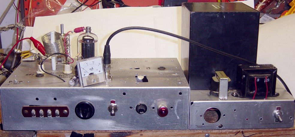
Here is the next phase in the development of this unit. For V1.5, I added a seperate chassis for the power supply. This was necessary because of the sheer size of the transformer! (The large black cube.) Overheating THIS puppy would take quite a bit of doing! :)
Click picture for larger view.
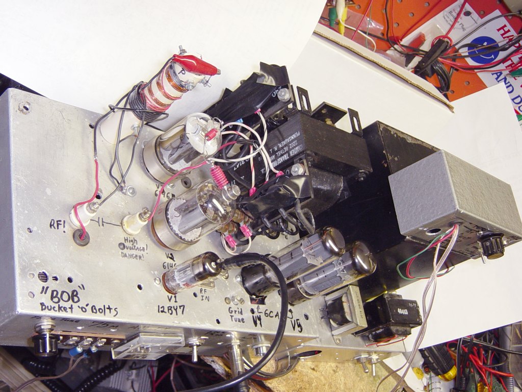
| Top, above view V1.5 - New power supply! |
 |
The small transformer (in front, right) is the screen grid supply, which is 270v. The big tranny did not have any taps at this voltage, so I had to add that as a seperate supply. The other transformer device is the B+ supply choke. The big tranny has multiple low voltage taps, and a CT 800v winding. In the CT configuration, this yeilds 565Vdc. I wired the unused low-current windings in series to get a -24V grid bias supply. The 6146 screen grids see 175v after a 25k resistor and 100K to gnd.
Click pictures for larger views.
| Front view V1.5 |
 |
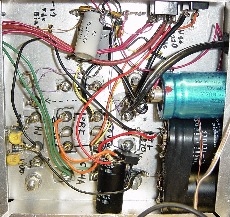
| Bottom of the V1.5 power supply. |
 |
You'll notice small disc capacitors across all of the HV diodes. This is absolutely essential in transmitters, to bypass the RF. This prevents a very noticable, raspy "hum" in the output, which is caused by the RF impedance changing with each cycle of the AC across those diodes.
The pair of B+ filter caps are in the lower right. 280uf 385v each, wired in series. The blue cap above them is the screen supply filter. It's seeing about 270v, which goes through a 25k resistor to the screen grid(s). The wires all exit from the upper left in this image. The thick red is B+. Med red is screen. Thin brown wire is control grid bias, and the green wires are for the filaments. (This power supply was modified on 2/25/2006 to boost the B+.) It provides 6VAC for filaments, -24vdc grid bias, +700 for B+ and +270 for the screen grid circuits.
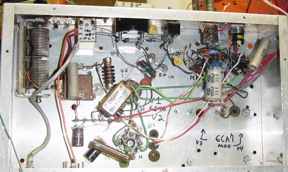
| Bottom of the V4.0 power supply. |
 |
The V1.5 power supply had remained unchanged until V3.2 on 2/26/2006. It was modified again to V4.0 on 3/4/2006 to boost the grid bias supply to -48v (Voltage doubler ckt used, visible at top, center.)
Also added a switch to kill both B+ lines while keeping filaments lit. (To left of main power sw, upper right.)
The 250v screen supply is now also the "low B+" for the 12BY7 RF driver.
In this photo, you can see how I've "split" the primaries, and I am now using the second one to get more voltage for the high B+ by rectifying & filtering it, and wiring it in series with the existing high B+ supply. I know it's not standard practice, but what about this transmitter is? ;) This boosted the high B+ from 560v to 710. (It sags to 650 under full load, which is less than 10% drop.)
With the higher B+, I'm getting 55 watts carrier with both tubes. You might be thinking "YOU CAN GET A HUNDRED WATTS!!!" That's true, but these tubes don't "grow on trees" anymore, so I run them easy to make them LAST! So far, I have had nothing but GLOWING reports on my signal and audio! (Pun intended! Hihi!)
Click picture for LARGE view.
| The "BOB" AM transmitter, V2.0 |
 |
The version 2.1 system was on the air from Feb thru May of 2005. The (now retired) exciter is behind "BOB", which now has both tubes, a redesigned output coupling circuit, and a few other minor mods. (This pic is version 2.0, with the wire spool RF output. That was replaced with a nice home-made coil in version 2.1.)
Instead of the tradional "Pi-Net" circuit, V2.0 & 2.1 use an air-core RF transformer. There are two reasons for doing this.
1) Both the primary and secondary are GROUND-REFERENCED
2) Only ONE tuning capacitor is needed!
You only need to tune for the dip in plate current, and you're done!
My absolute max output with that design was 30 watts, CW. (At 575v, the B+ was a little low.) With this version, I could only get about 12 watts carrier to see 100% positive mod. I included the O'scope in the pic, just to "show off" the nice envelope! ;) The sinewave is actually being generated by accoustic feedback, and it was varying, so that is why it is not 100% in this picture.
If you click this pic and view the LARGE version, you will see some text that I added to the image, pointing out what some of the items in the picture were.
The N1NKM Homebrew
AM station! (V2.1 in 2005) |
 |
(Click pic for large version.)
Here's the AM station, with the homebrew receiver! (The former exciter is not in this picture.) That receiver is another "pride & joy" project! (Built on 5/7/2005) I took a very filthy old Johnson Messenger CB rig and converted it into a nice AM receiver for 75M! It's range is limited to only 3865-3910, because I wanted to be able to tune the AM window, easily, without needing a big dial! The small knob and hand-drawn markings are more than adequate. (I later added a BFO for SSB reception.) That receiver, while "nifty", is just not up to the task of pulling in weaker signals in this very RF-noisy neghborhood. I need DSP to clean things up, so I normally use the Icom 718 for the rx.
| My homebrew 75M AM RX! |
 |
This is the bottom of the AM receiver. It required some fairly extensive mods to convert this unit from a CB into a 75M receiver! ;) I changed several coils, reworked the audio stages (using the mic preamp as a cathode-follower to drive the new, lower-value volume pot. See little green caps in lower left corner) converted the TX x-tal osc into a local osc, and removed the RF final. I also had to put a 1.5K resistor into the B+ supply, because it was much too high! (About 400v) All of the tubes were getting VERY hot. Now the B+ is 300v and everything is happier. :)
| 75M AM Receiver - bottom view |
 |
(Click pic for large version.)
Here is the top view of the receiver. The crystal deck is gone, the final and rectifier tubes are also gone. It needed a new B+ filter cap, which is clearly visible next to the tranny.
| 75M AM Receiver - top view |
 |
(Click pic for large version.)
| V2.0 of Exciter (Obsolete in 2006) |
 |
This is the 100% homebrew RF exciter. (Now, QRP AM Transmitter.) Everything, from the VFO to the modulator & 3w RF output stage is homebrew and uses salvaged or surplus parts. This is now V2.0 of the exciter, because I have added several more switches and a PTT system. (Apply 12v to the PTT line to key it.) The development of the exciter is complete at this point, as there really is no room for further improvement, IMHO. :) It's a nice stand-alone transmitter in its own right. (It has been made obsolete by further enhancements to B.O.B. which includes a PLL synthesized VFO!)
Those switches allow me to activate various stages independently for testing, experimenting, tuning, etc. The most useful switch keys only the VFO, so that I can "spot" my signal on the receiver. It allows me to easily and quickly zero-beat a station so that I will be centered on their frequency. There is a little drift, but not objectionable on AM.
The small box on top is the mic preamp and PTT control relay. The relay converts the pull-to-ground PTT of the D104 into a +12v signal to energize the relays in the exciter, transmitter, and T/R switch. The mic preamp/audio driver is the only solid state portion of this whole transmitter! (It is the salvaged audio amp portion of a lightning-fried computer's sound card. BTN!!) It is capable of producing about 2 watts of audio, but only needs to push a few dozen milliwatts into the exciter to drive the modulator.
2006 UPDATE: This solid state unit (small box, sitting on upper left) now provides the audio drive to the "BOB" V4.0 modulator stage, instead. The exiter provided 3w of unmodulated RF to the TX. On 5/24/2005, I started using my digital RF generator instead of this homebrew exciter. It is digital and never drifts! It's 100mw output is sufficient to drive the "B.O.B." V4.0 AM transmitter. Thus, this exciter is no longer used for that purpose. I later replaced that signal generator with a homebrew PLL VFO/receiver unit, which is now a permanent part of this B.O.B. transmitter! ;)
You can click this link to see more details about this homebrew QRP transmitter. :)
Here we are with a major revision of the project!
A PLATE MODULATOR! :)
| V3.2 - 50 watt AM TX! |
 |
(Click pics for large versions.)
Not bad for a pile of JUNK, huh? Mad Max would be proud!
This is version 3.2. It includes an onboard modulator and delivers a solid 50 watt carrier! (V3.1 was only 30 watts) A pair of 6CA7's working push-pull into the 500v CT (secondary) winding of a 208v (primary) power transformer provides more than enough power for 100% modulaton. (The 208 winding is in the B+ line to the finals, tapped at the -10 point. It is thus equivalent to a 198v winding. It's working, that's the main thing!) In upgrading from V3.1 to V3.2, I wired the 6.3 v filament winding into a negative feedback ckt, to reduce distortion.
The modulator tube grids are fed by one of those tiny Radio Shack 8 ohm to 1k CT audio transformers. It provides a nice input impedance match & phase splitting for the push-pull modulator.
ANYWAY... It's been tested on the air, and the reports are that it sounds great! :)
Below are a few more pics of version 3.1 of the unit. (3.2 has several new resistors visible.)
| V3.0 AM TX side view |
 |
(Click pics for large versions.)
In V3.1, I moved the meter down into the chassis, where that unused AC outlet was. I also added a T/R switching relay with cathode steering diodes and a BNC connector which feeds the receiver. The PTT line connects to a terminal on the screw terminal strip.
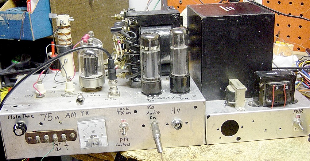
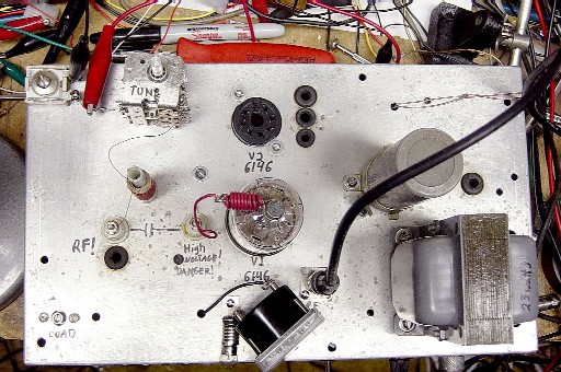
| V4.0 Side. Click for large view! |
 |
Here you can see some significant cosmetic improvements! The meter is now inside the chassis, where it belongs. The 12BY7 RF driver is just in front of the two 6146 finals.
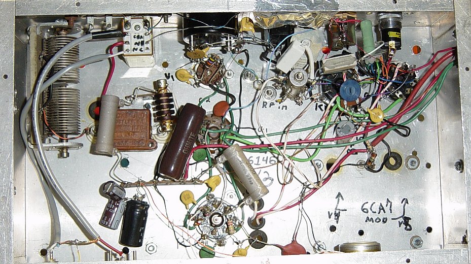
| V3.1 Bottom. Click for large view! |
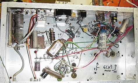 |
Yeah, my wiring is messy... but the point is to make it WORK, not make it pretty. Remember- I built this thing from JUNK! ;)
| V4.0 Bottom. Click for large view! |
 |
B.O.B. 4.0 Schematic
| V4.0 AF section Schematic. |
 |
| V4.0 RF section Schematic. (Click for large view.) |
 |
Back in fall of 2006, I added a band switch to allow use of this unit on 60 meters, where it functions as a linear amplifier. With the RF generator providing a nice, 2.5Khz band-limited SSB signal, this is perfect for those 5 channels we presently have. I get 40 watts PEP so I was well within the limit. :)
Ahhh... now we've gotten to the GOOD part! :)
| The V4.3 "B.O.B" SYSTEM's new digital VFO V2.0 |
 |
Here is PHASE TWO of the design & implementation of the new receiver/VFO. I've created an "address translation table" in an EPROM to translate the binary output of those numeric thumbwheel switches into the correct binary code for the PLL to correlate it with the frequency shown by the switches. The operation is so simple, it's elegant! :) The LED digit display shows either 0 or 5, for the 5Khz, which is controlled by a toggle switch. (Not shown.)
If you look carefully, you can see that the operating frequency is 3.885 :)
The EPROM is encoded to only operate the PLL from 3500 to 3995. Outside that range, the VFO output is disabled, and the PLL goes "on vacation" until a valid frequency is dialed in. Since only 7 bits were needed to give me the 500Khz range, I used the LSB of the EPROM to control the RF output stage. Only valid frequencies will enable it.
With the EPROM running steady-state, there is no clock, no noise. No need for a CPU... the thumbwheels are connected to the address lines of the EPROM. I whipped-up a GWBASIC routine to generate the proper sequence of bytes, and burned them into the EPROM. It took a couple tries to get it right, but once I had it working, I was VERY happy with the results! There is a red/green LED just to the left of the EPROM, for tx/rx indication. (Hey, why not??)
I've so thoroughly modified this former CB, that it is certainly fair to call this a HOMEBREW receiver/VFO! :) Now, all this baby needs is some kind of decent cabinet, so all of the controls & display are mounted nicely.
(By itself, this unit WILL work as a very QRP CW transmitter. It just needs a BFO for receive.)
Sure, this COULD have all been done with modern chips... but WHY NOT re-use some of this good old 1980's technology? (ESPECIALLY when I already have a BUNCH of this stuff just collecting DUST!) You can usually get 2732 EPROMS as throwaways, now! I probably have several dozen of them!
More details about the development of this HyGain CB board PLL system can be found HERE!
SOMEDAY, I hope to put this into a much better-looking case! ;)
With my ribbon microphone connected to this "B.O.B." station, I can now say, with absolute truth...
"This station is HOMEBREW, from the microphone to the antenna!"
| Homebrew ribbon mic, "Delta II" |
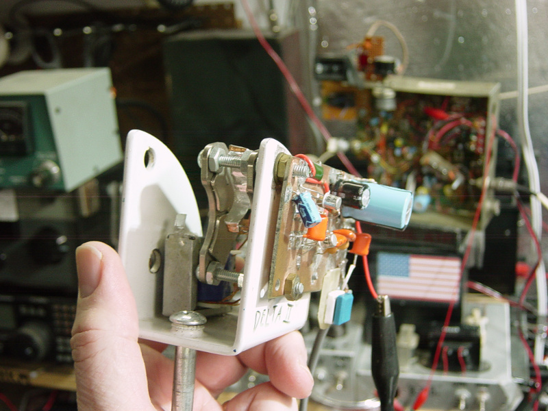 |
For HOW TO BUILD THIS, click HERE! :)
Important notes about TUBE POWER SUPPLIES:
Get some good, HV rated diodes. I have some that are rated for 1Kv that I use, but I use two, in series, with 1M ohm resistors across each diode. A .002Uf cap goes across each set. (You treat each pair of diodes/resistors & cap as if it were a single diode.) This does several things- it balances the reverse voltage across them and bypasses RF.
You ALWAYS want to put ceramic disc capacitors across the rectifier diodes in ANY transmitter! Failing to do this will result in a nasty buzz on the air. Why? Because as the diodes do their job of rectifying the AC power, that causes the RF to find a slightly different path for each 1/2 cycle of the 60Hz power. The caps cause the RF to bypass the diodes, so that their switching action doesn't do that to the RF.
Usually, to really get rid of hum, you want to use a choke. Several Henries, minimum. Make sure it can handle the current you'll be drawing. (figure 150ma per 6146 as a maximum) BTW, you DO NOT want to be running the 6146's with their plates glowing! I know they'll "handle it" OK, but they will not last very long! You want to be fairly GENTLE with them, to get as many years as possible... they don't exactly "grow on trees" anymore, after all. ;)
So you have the power transformer. That feeds the rectifer unit. A small capacitor there (a few microfarads at the required voltage) then the choke, then more capacitors. You want at least a few dozen uf, up to no more than a couple hundred. The more, the better, within reason. (You would NOT want 10,000 uf!) A good general value would be around 200uf for a 600v supply. You always want the caps to have a MINIMUM of 50% higher voltage rating than your supply delivers. (Safety margins! You do not ever want these things exploding!)
Another benefit to using solid-state diodes is that you're not wasting power to heat more filaments, and they will drop far less voltage under load. Putting a small resistor (47 ohms or so for ~200 ma supplies) between the rectifier and that first cap is a good idea. At 200ma current, that will drop just under 10v, which is insignificant. The main point of this small R is to reduce the SURGE CURRENT when you first apply power. It also reduces the PEAK power through the diodes which happens with each cycle of the AC mains. If you're going to use three 6146's, you want to drop the value of that R to 33 ohms. Four 6146's, drop it to 22 ohms.
You should be able to find PLENTY of schematics out there to help you with the actual circuits needed. Hopefully, what I've given here will get you going down the right path. BE CAREFUL, because those voltages are potentially LETHAL! (Not to mention QUITE PAINFUL!)
Just a little "rant", here...
If you're one of those guys who would call this "PW", save your breath! Please. If you don't want to talk to me or hear me, don't answer my CQ or join my QSO... and please, for Pete's sake, don't jam me, OK? Just dial your VFO to another frequency and have a QSO with someone else. Keying up on me & those I am in QSO with doesn't prove anything. (Does it somehow make you feel "manly" to be able to clobber a 50 watt signal?! Get a life, man. Get a life.)
- The Wouff Hong -
It once struck terror into the hearts of LIDS, everywhere...
Whatever happened to this instrument of law and order??
|
If we are causing you QRM, just TELL US and we will QSY. Many times, I will QSY BEFORE being asked... if I am receiving QRM from you, then it's possible you may be receiving it from me... so in keeping with GOOD AMATEUR PRACTICE, I will QSY. This is something we should *ALL* strive to do. QSL?
Oh, and one more thing... while I do derive considerable enjoyment from my HOBBY of Amateur Radio, I really honestly DO have a LIFE. If malcontents and rule-breakers want to TRY to make my life miserable, they WILL NOT succeed! Why? SIMPLE... this transmitter (and all of my other radios) have an OFF SWITCH! Oh, and guess what? I know how to use them, and I will! If jamming me gives you some kind of kick, knock yourself out. I will just LAUGH at you, give my callsign to be legal, then shut the stupid thing off, and go upstairs. I have plenty of other things to do that I enjoy just as much (or more) as Ham Radio. I will adjust my schedule to operate when you are NOT on the air. There are PLENTY of really decent, intelligent, respectable people on the air with whom I will gladly QSO... People who have NO PROBLEM copying my 50 watt signal.
That's it for my soapbox.
You are welcome to E-mail me with comments/suggestions.
Constructive messages are welcome.
Abusive messages will be deleted. It's that simple. :)
Here's my HOME page
*** DISCLAIMERS ***
(Keep the lawyers happy.)
*ALL* Information presented here is done so without warranty or guarantee of any kind. Author assumes no responsibility for the use or inability to use this information. Author also assumes no responsibility for the ability or inability to complete the projects, above. This project uses potentially *LETHAL* voltages! If you are not sure of what you're doing, ask an experienced friend to help. ALWAYS "pull the plug" and ground the caps to make sure there is *NO HIGH VOLTAGE* when working with this unit! Keep it well out of easy-reach when operating, or attach a cover to keep hands away from dangerous voltages.
This information is presented as educational information only. No guarantee is made as to its fitness for any purpose. All risk is assumed by the person who choses to use this information. While the author's experience indicates that this proceedure was effective, any attempt to build/modify these devices IS AT YOUR OWN RISK. Extreme care must always be excercised, this is at the builder's SOLE RISK.