God Bless America!
N1NKM's

Ribbon mic page 2 |
 |

HOMEBREW ribbon microphone BETA
Latest updates: 1/6/07
Beta unit modified. Preamps on both the Beta & Gamma units upgraded with low-noise transistors & a few other component changes/additions.
Others in this series:
ALPHA UNIT (Page 1)
GAMMA UNIT (Page 3)
DELTA UNIT (Page 4)
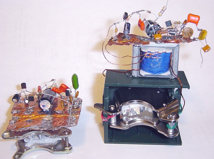
| "Family Portrait" Beta V1.0 and Alpha units |
 |
Now that I have replaced the transformer of the Prototype (making it the Alpha Unit) its two-stage preamp is giving me plenty of output. The noise is still significant, so there is no question that I will be needing to use LOW NOISE transistors. (They were ordered from Mouser on 12/27/2006.) The alpha unit works much better, but the audio quality is still not on a par with the two new units. Beta V2.0 is nearly as good as the Gamma.
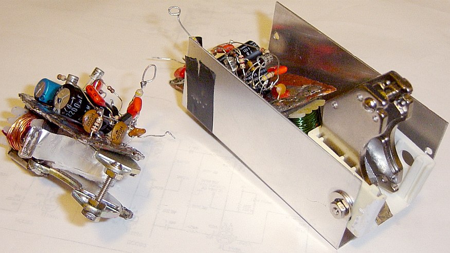
| "Family Portrait" Beta V2.0 and Gamma units |
 |
Version 2.0 of the Beta unit has the ribbon reoriented so that it is perpendicular to the magnet structure. This exposes it to a uniform magnetic polarity. It also made mounting the ribbon much better and easier! One side is attached to a stiff copper wire that has been fastened to the copper base. The ribbon is slightly concave, with the indent facing the front, where one would address the mic.
SECOND homebrew ribbon mic; BETA Unit v1.0 & 2.0
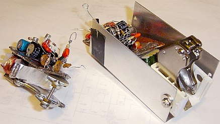
| Beta unit, V1.0 rear, oblique |
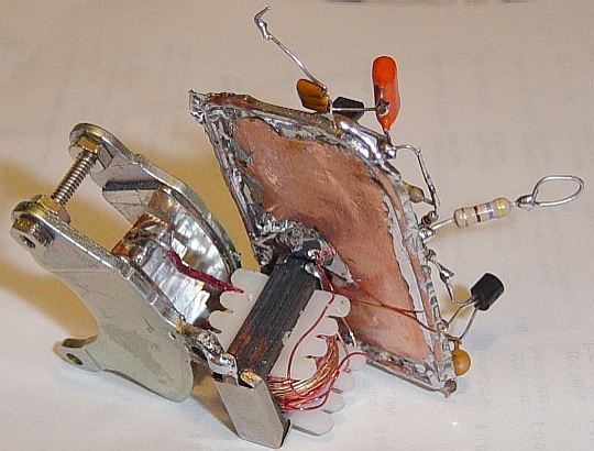 |
This mic also uses a custom wound audio transformer. (Scavenged from a CB.) This one has a much higher step-up ratio, however. It uses about 6 turns of #14 wire on the primary, and quite a few turns of #24 guage wire for the secondary. The output of this mic is considerably higher than the prototype!
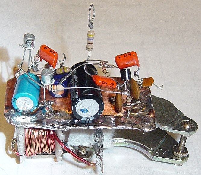
| Beta unit V1.0 top, oblique |
 |
As I look at it in this photo, I can't help but think of Geordi's visor from Star Trek! ;)
| Beta unit preamp schematic V1.0 |
 |
Since I still had the first ribbon from the protype unit, and I had another magnet set, I decided to try my hand at building another one from scratch. Here it is... Beta unit, V1.0! In this version, the ribbon had pretty tight folds. I flattened-out the original folds, then re-folded it back & forth. These folds are maybe about 3/16" each. The ribbon, itself, is about 5/16" wide. Like the protype, these magnets are also about 1/2" apart. Everything is soldered together to ensure very solid grounding. Hum pickup is purely by magnetic induction. Since the primary of this tranny is using a much heavier guage wire and fewer turns, the step-up ratio is quite a bit higher. Also, the stiff wires are perfect supports for the ribbon, itself! Here, there is a little bit of tension on the ribbon. (The protype has virtually no tension.)
During another conversation with Stu, AB2EZ, he suggested a small bit of tissue gently pressing against the ribbon, to attenuate the "ringing". (AKA: The "aluminumy" sound!) IT WORKS! I've replaced the tightly folded ribbon you see above ,with one that only has 3 shallow folds, and put a smal bit of soft tissue between the ribbon and magnet. He said that it was a 500% improvement, and actually sounded respectable. Not perfect, but certainly MUCH more listenable than it was! So, progress continues!
UPDATE: 12/12/2006
Now that I've built this HEADPHONE AMP, I've been doing a lot more testing. There is a DRAMATIC difference in audio quality with and without the tissue! The physical location of the tissue is also important, as it changes the audio quite significantly! I also experimented with a MUCH THINNER piece of foil that I saved from a candy wrapper. (So thin, it's almost impossible to work with without crumpling or tearing it!) I had expected BETTER audio... but that was NOT the case! It was MUCH LOWER in volume, and even more "aluminumy" than the slightly thicker foil. So, the ribbon with the 3 shallow folds is back, along with the tissue. (The tissue did little to help the super-thin foil. Go figure?)
Each of these mics have been used on the air several times.
Someone has requested an audio file of what this sounds like...
HERE IT IS! (Beta unit V1.0, B.O.B. transmitter, recorded off-air in NH.)
| Beta unit V1.5 front |
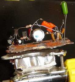 |
An interim version of the BETA unit.
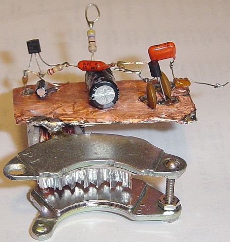
| Beta unit V2.0 back | Beta unit V2.0 Front |
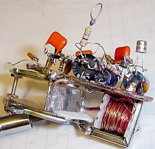 |
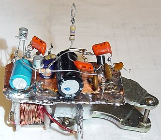 |
(Click images for large views)
UPDATE: 1/6/2007
Here is the most recent revision of the BETA unit, Version 2.0 (with the 2.2 preamp) I've reoriented the magnets and the ribbon. This has improved the Beta Unit's performance to be nearly equal to the Gamma unit. :) The ribbon now only crosses through the end of the magnets so that it sees a uniform pole. (Similar to the Gamma Unit.) As a result, the beta unit now sounds almost as good as the Gamma. (Beta still needs the bit of tissue, tho.)
UPDATES: 2.0: 12/27/2006, 2.2: 1/6/2007
| Beta unit preamp schematic V2.2 |
 |
Here is the upgraded (again, 1/6/2007) ribbon mic preamp. (Beta, Gamma, and all future units.) It has so much gain that it needs the 100 ohm R to the emitter of Q3 and the 10K (changed to 8.2K in V2.2) feedback resistor from E of Q3 to E of Q1. The gain is now more useful, and it also helped reduce the transistor noise. There was still quite a bit of hiss, so I have replaced Q1 and Q2 with very low noise transistors. It decreased the noise, noticably. I also changed the collector and base R's on Q1, and added another stage of isolation to the Vcc supply feeding Q1 and Q2. This reduced low frequency "ringing" which I originally thought was the ribbon, itself. Now that the preamp is at V2.2, I don't think I will be needing to change it further. This is the best preamp design, so far! Much less noise, PLENTY of gain, and good clean audio. Can't beat that!
With preamps that have as much gain as this, power supply bypassing and isolation are ESSENTIAL. That is why there is a 470 ohm resistor feeding the 12V into this unit. (and in V2.2, another 1K and 220u feeding Q1 & Q2) Without it, even the smallest noise on the supply rails gets picked up and amplified. This will result in feedback or other obnoxious effects. It is quite surprising, in fact, just how sensitive these circuits become to even the tiniest noise on the supply rails! Thus, if you planned to power this mic preamp from the same 13.8V supply as your solid state rig, you'd have all kinds of problems. With these R/C isolation ckts, those problems are eliminated.
This preamp has SO MUCH GAIN, it could probably be used as a tape head or magnetic phono preamp. You just need to use low noise transistors for the first two stages. The gain can be set by using a different value for the "flying" 10K resistor (2.2K-100K) and the Q3 emitter resistor. (10ohms-220 ohms) (They work a little like the feedback network in an op amp ckt, but not nearly as precisely!)
"Stay Tuned!" ;) There's still MORE TO COME!!
(I will keep updating this page as I make progress with this unit. Check back now & then.)
Others in this series:
ALPHA UNIT (Page 1)
GAMMA UNIT (Page 3)
DELTA UNIT (Page 4)
Take me HOME...